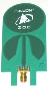
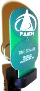
This piece from Popular Mechanics on the evolution and development of the Leatherman Tool inspired me to draft this post about the evolution of one of my UWB antenna designs from conception, through prototyping, and finally to production. This paper describes the end result, and the design is covered in one way or another in U.S. Patents 6,512,488, 6,642,903, and 6,845,253. I performed the work described here 2000-2002 while employed by the Time Domain Corporation.
The idea started as a planar elliptical dipole antenna (described here). With the feed point in the middle of the antenna, the coaxial feed line had to be routed in an awkward fashion from the center of the antenna down to the RF device. Such a design does not integrate well with RF electronics.
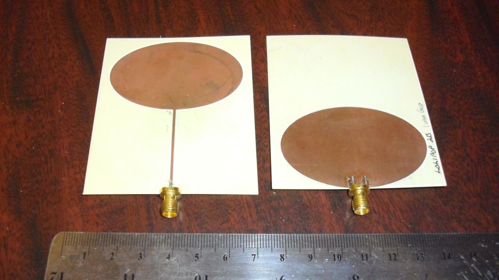
The next step was to concoct a way to feed the antenna using a conventional stripline. I devised what I called a “Lollipop” dipole, feeding the top element under the assumption that the bottom element could be treated as a ground plane. I no longer have access to my results, but as I recall the unbalanced-to-balanced transition yielded unreliable performance with excessive reflection.
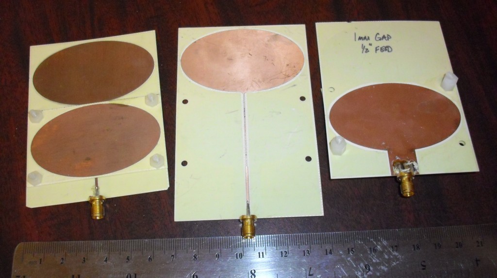
The next approach I tried was an embedded stripline. This too did not yield satisfactory results. I became convinced that a suitable feed structure would require some kind of impedance transformation.
My next design employed a tapered stripline. Although I did not know it at the time, my design concept was essentially a planar cross-section of a very famous UWB design – the Lindenblad element. Nils Lindenblad designed this element for RCA to use in television broadcasting in the 1930s. RCA’s centralized scheme for television involved multiple stations being transmitted from the same transmit tower – hence the need for a UWB element. Ghosting, then as now, is a serious problem for television, so a very low VSWR was a requirement. Lindenblad’s design (U.S. Patent 2,239,724) was a beauty of both art-deco design and the RF arts. Alas my planar version was not up to Lindenblad’s standards.
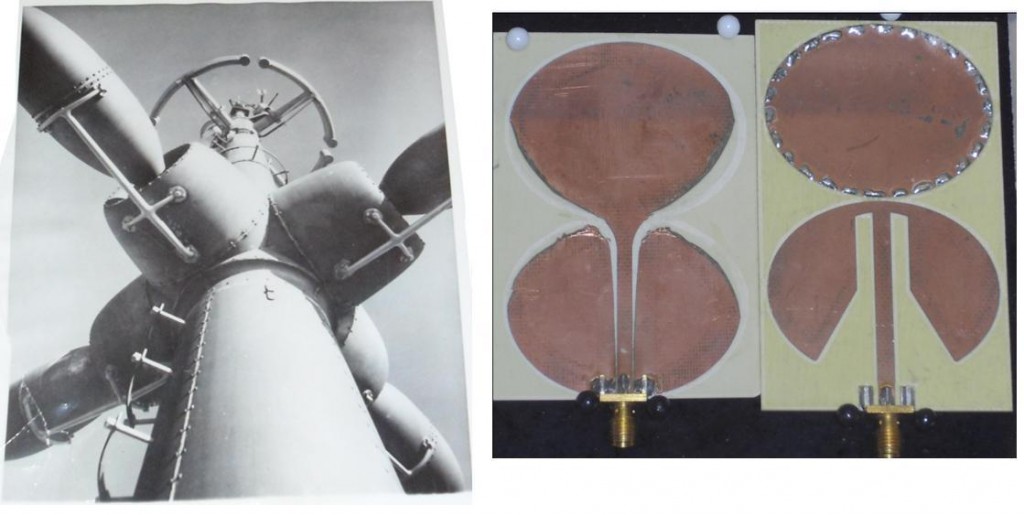
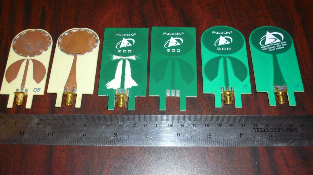
The final (and successful) dipole architecture employed a tapered balun impedance transformer. The figure above (right) shows one of the initial designs. The “stitching” around the edge simulates using vias to connect a top and bottom metallization. I used a combination of HFSS simulations and milled prototypes to converge on a final solution. I was taken by surprise when the initial production prototype failed to meet my performance specifications. This was because the milled prototype took away just enough of the printed circuit board material around the conductor to perturb the impedance. A few slight adjustments, and the final design was done.

4 thoughts on “Birth of an Antenna: From Conception to Production”
Cool post Hans.
This antenna looks familiar. It was a good antenna but I think the low end frequency range could have been easily extended by having two symmetrical shorts on the feed arms or “leaves” as I call it in my thesis.
Also I think the pattern which had a 3 dB ripple could have been removed with a parasitic element at the cost of 200 MHz of bandwidth.
None the less a true Hans product :)…
Thanks, Arun. Our former colleague Dennis Troutman, had the same idea. He suggested an inductive short which did indeed extend the bandwidth. His Idea was never implemented in production antennas so far as I know.