Apple has been justly criticized for not responding promptly to the iPhone’s antenna problems, and for problems in the way they handled the crisis. But with so many piling on Apple for their iPhone antenna problems, I’d like to reiterate and expand on what I said Monday:
The antenna design on the iPhone really is quite clever and innovative. By using a significant portion of the bevel around the device, Apple antenna engineers made a much larger – and therefore probably more sensitive – antenna than the typical Planar Inverted F Antenna (PIFA) used in most cell phones. This enhanced antenna sensitivity means less transmit power to talk, longer battery life, and enhanced reception in weak signal areas. Of course the downside is the increased sensitivity of the antenna to hand placement, but the bumper solution seems an easy fix. Why wouldn’t an iPhone owner want a bumper to keep their device from getting scratched anyway?
An exterior or enclosure antenna is a good way to maximize antenna size (and thus performance) for a compact device of a particular size. The secret to making an exterior antenna work is to provide enough dielectric loading on the exterior to insulate the antenna conductor (but not so much as to narrow the bandwidth). This blog post discusses the origins of Apple’s iPhone enclosure antenna concept in the early days of the space age.
The earliest deployment (that I’m aware of) of an enclosure antenna was on the Explorer series of satellites – the first U.S. satellites in orbit. I had the story from two very senior engineers, Warren Hopper and Tom Barr, who implemented the design in 1957. Almost fifty years later, they were still working in RF engineering for SAIC in Huntsville, AL. I was unable to validate their story at the time, so I mentioned it in my book (see p. 246), but did not provide additional details. Here is what they told me.
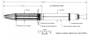
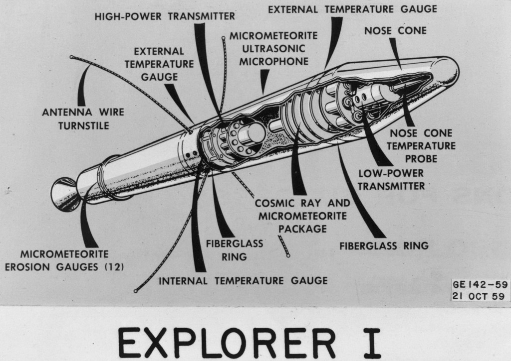
The U.S. launched Explorer I into orbit in January 1958. Barr and Hopper designed an innovative antenna by incorporating a fiberglass slot in the exterior cylindrical conducting enclosure. The slot isolated the enclosure sections so one side could be driven against the other. They actually had two such slots, dividing the antenna into three sections. They reported, however, that the CalTech engineers responsible for the satellite were skeptical their antenna would work properly, and insisted on also adding a back-up antenna system: four wires fed in a turnstile configuration.

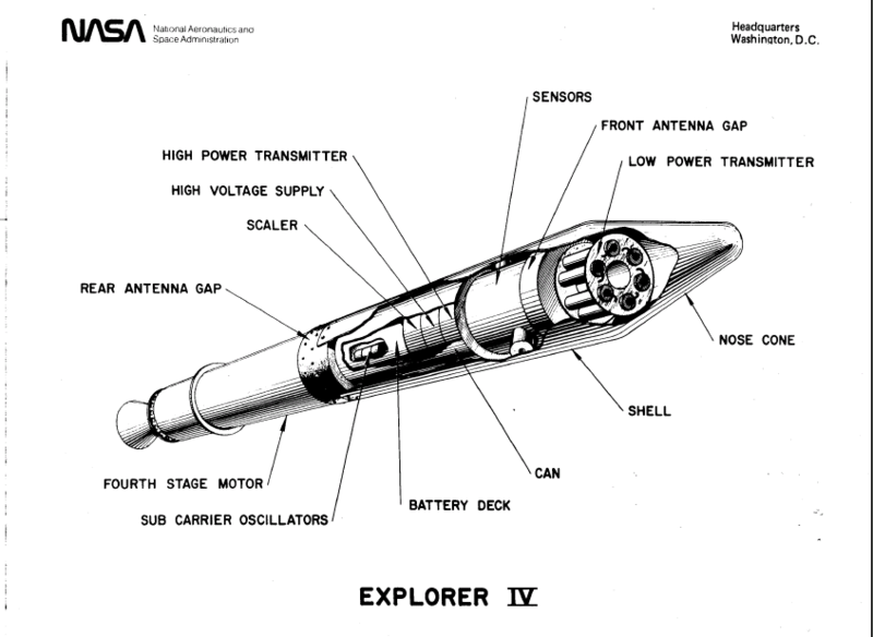
The rotation of the satellite along its long axis was to act to keep the turnstile antenna fully deployed. When Explorer I flew however, the satellite tumbled end-over-end instead. Barr and Hopper attributed the tumble to the CalTech antenna. I’m skeptical. By the time Explorer IV flew, however, Cal Tech had abandoned the turnstile concept in favor of Barr and Hopper’s enclosure antenna.

The Explorer satellite enclosure antennas, invented by Hopper and Barr over fifty years ago, are analogous to and precursors of the iPhone antenna design. The troublesome black line in the iPhone bevel corresponds to the fiberglass slot. Of course in space, Hopper and Barr’s implementation did not have to withstand fingers electrically connecting and shorting out the gap. In full disclosure, I invented something similar in my “nano-antenna” design for a UWB transmit sensor (U.S. Patent 7,068,225), so I’m favorably inclined to attempts to minimize device size and maximize antenna performance by using an antenna conformal to a device exterior.


